|
GOVERING an area of 40 acres, the Works have ten berths for the
construction of ships of all sizes, with departments for producing all the
accessories and machinery—engine and boiler works, steam-turbine factory,
foundries, brass, copper, and sheet-iron shops, saw-mill and extensive
wood-working department— and these give employment to four thousand
workmen. The equipment has been greatly extended and modernised during the
past few years. The building of the China Steam Navigation Company's
steamer Fengtien in nineteen weeks, from the laying of the keel to the
trials, is one of several instances of rapid construction which might be
enumerated.
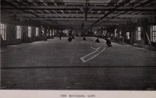
The plans of ships prepared in the designing department and drawing
offices, to which reference has been made in the previous Chapter, are
passed to the moulding loft, where the work of construction is commenced.
This loft is situated in a substantial four-storey building, accommodating
practically all the wood-finishing departments. Each floor has an area of
12,500 square feet; the ground and first floors are given up to the
joiners and cabinet-makers, with their numerous machine tools, while the
top floor is at present utilised for storing completed joiner work, etc.
The moulding loft monopolises the third floor, and as the length is 240
ft. and the width 52 ft., there is ample space, as is shown on the
engraving in Plate XL., facing page 94, for laying down full size
deck-plating, stringers, margin plates, deck girders, etc., so that moulds
or templates may be prepared for the iron workers. Armour-plates for
warship belts, barbettes, and casemates are similarly prepared in
template, to assist the makers to form them to the required curvature and
size.
The ironworkers' department is extensive and important. When the material
is delivered into the yard, it is discharged from the railway wagons by a
5-ton electric overhead travelling high-speed crane, which stacks the
plates and bars in such a way that any piece can be readily removed by the
same crane for conveyance to the furnaces.
There are six furnaces suitable for heating shell plates of the largest
size, and angles and bars for frames, etc., up to 60 ft. in length.
Adjacent to the furnaces are the screeve boards and the frame-bending
blocks. The channel, bulb angle, or Z bars, used so extensively now for
framing in large ships, are bevelled as they pass from the furnace to the
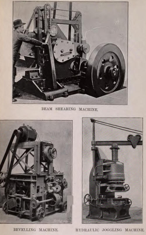
bending blocks. This is done in a special machine made by Messrs. Davis
and Primrose, Leith, and illustrated on Plate XLI., adjoining this page.
The bars, as delivered from the rolling mills, have flanges at an angle of
90 deg., which is not suitable for taking the skin plating of ships. One
angle has therefore to be altered, so that while the inner flange may lie
at right angles to the keel-plate, that to the outside will fit closely to
the shell plating throughout the entire length of the frame from keel to
shear stroke, which may be 50 ft. or 60 ft.
As the bar passes through the machine, the web is carried on an ordinary
flat roller, while bevelling rolls, set to the desired angle, work on each
side of one of the flanges to give it the desired set. There are several
of these machines in use, and they run on rails laid across the front of
the furnace, so that the angles, Z sections, or channels may be bevelled
while passing out of the furnace on to the bending blocks. The
manipulation of the plates from the furnace is by means of steam and
electric winches.
Formerly, the turning of the frames to the required curvature against the
pins on the bending blocks was carried out by hand. To suit the heavier
scantlings of the larger ships of the present day, a portable hydraulic
machine is now utilised. It is fixed at its base by pins, which fit into
the ordinary holes in the blocks, and hydraulic pressure is supplied
through a flexible pipe to work the ram-head against the angles, forcing
them to take the desired form. The machine is a great labour economiser,
as it ensures work on the heaviest of bulb angles being carried out in the
minimum of time, and therefore at top heat.
The bars are usually cut to
length by a guillotine, but it was considered that this tended to twist
the metal, and perhaps unduly fatigue it; and as a consequence the firm
have fitted John's shearing and notching machine, as constructed by
Messrs. Henry Pels and Co., of Berlin. This new machine is illustrated on
Plate XLI., adjoining page 95. The tool is shown in the act of cutting
through a channel section. The cutting tool is seen immediately in front
of the operator, and is actuated by gearing accommodated within the
standards of the machine. When the cutting tool is brought down on the
angle or beam to be sheared, and the shaft at the rear started, the
rotation of an eccentric actuated by the shaft causes the point of the
tool to slide icily a short distance to-and-fro on the bar. The hand lever
on the right hand side of the machine is depressed, forcing the tool
downwards, and the continued rotation of the eccentric causes the tool to
pierce through the bar with a downward and inward motion. Where there is a
deep web with flanges, the beam is reversed on the anvil, to enable the
other flange to be cut. The cutting of any bar in this machine is a matter
of only a few seconds.
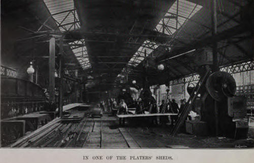
10 horse-power motors. There are channel-angle shearing machines, taking
work 16 in. by 6 in., and operated by hydraulic pressure. These machines
are made with revolving gear to suit almost any angle of flange.
There is also an hydraulic stamping press for bending angles and tees to
form knee-bars and other stiffening pieces, the cylinders being 14 in. in
diameter, working at a pressure of 800 lb. per square inch, with a stroke
of 18 in. The machine, which has been constructed by Sir William Arrol and
Company, Limited, consists of an hydraulic cylinder mounted horizontally
on a massive table. On the ram-head there are former blocks, while on the
table in front there are corresponding dies. The bar is placed on the
table between the blocks and dies, and as these are forced together by
hydraulic pressure, the bar between them is squeezed into the exact shape
required. Not only is the operation expeditiously executed, but there is
no uncertainty. The whole of the metal within the bar is retained inside
the knee, which becomes thicker and broader, materially adding to its
strength. As the moulds or dies can be made to suit any form, the machine
can be utilised in the preparation of various details of structures,
provided they are designed with a view to their production by aid of dies.
The great economy resulting from the use of special machines is only
realised when the designing staff remember that they innet be kept
employed.
A specially powerful tool is provided for bending channel irons and beams,
and for drilling horizontal holes in them. Hydraulic manhole-punching and
flanging machine, are employed, each having a ram of 27 in. in diameter,
uid capable of punching a hole 42 in. by 16 in. through a plate I in.
thick. There are provided dies for forming flanges 4 ft. 6 in. deep in the
widest of plates.
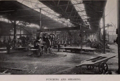
The modern practice of joggling and of scarfing the laps and. edges of
plates is applied in many instances, and special hydraulic tools are
provided to carry out this work. The firm were also early in adopting the
practice of joggling frames, deck beams, etc. The frames and beams are
joggled when cold, to suit each alternate inner strake of plating, in a
special design of hydraulic press, of which there are several in the
works. This tool, illustrated on Plate XLI., adjoining page 95, carries
dies on the ram-head and on the anvil, to form between them the obverse
and reverse sides of the dent or joggle desired. Movable centre-pieces on
the ram-head and anvil are traversed in all directions by screw thread to
suit the position and width of the joggled part, and a gauge shows
variations of 0.1 in. in the position of the joggled part of the frame. A
2 ft. length of angle can be joggled at each stroke. The machines are by
Messrs. Hugh Smith and Co., Limited, Glasgow.
The same machine joggles the lap or edge of a shell, inner bottom, or
deckplate in a similar way. The, whole length of the frame or plate can
thus be worked in a very short time. A powerful jib crane, of 16 ft.
radius, assists materially in the rapidity of the work turned out by these
tools. The only slips required are at the ends of the vessel, where the
bevel of the frames precludes the use of joggling. A special
electrically-driven hammer is used for forming these taper slips.
The angles, etc., to form the frames are assembled at the head of the
building-berth, and when lying on skids are riveted to form the double
bottom, frames and margin plates. Hydraulic riveters are used wherever
possible. There are about a score of these at work in the shipbuilding
yard, with cylinders from 8 in. to 101 in. in diameter, a stroke of 71
in., and a gap of 55 in., so that heavy work can be done. Some of them are
specially designed for keel work, for closing rivets in beams, and for
difficult parts.
The frames thus riveted are conveyed down the berth by a simple and
ingenious cableway, known in the Works as the "switchback," from its
resemblance to the well-known amusement railway. A derrick-post stands at
the head of the berth adjacent to the skids on which the frames are
riveted. The cable stretches from a small derrick at the foot of the
shipbuilding berth over a pulley at the top of the large derrick-post, and
thence, through a similar block at its base, to an electric winch. The
frame or unit of the ship's structure is suspended on a running block on
the cable, which is then made taut, partly by the working of the winch and
partly by the large derrick post being inclined backwards. The running
block with its load travels down the taut cable by gravity, under the
guidance of the squad of fitters. The gradient of the cableway is only
sufficient to enable the load to move slowly to its position in the
shipbuilding berth.
The double -bottom frames and margin plates are united with the
keel-plate, and subsequently there are successively worked into the
structure the tank top plates, side frames, the skin plates, beams,
bulk-heads, and other units, portable hydraulic punches and riveters being
largely used. Pneumatic tools are also extensively employed for boring,
drilling, riveting, chipping, caulking, etc. There are from 130 to 140 of
these tools in use on vessels in course of construction.
There are ten building berths ranging in length up to 700 ft.; but slight
alterations would enable the firm to build vessels of still greater size.
Several of these are shown on the engraving on Plate XXXVII., facing page
88. The launching ground is probably the finest in the river, the channel
being here of great depth and very wide, as is shown on the engraving
opposite. Indeed, ordinary merchant vessels with full lines are launched
without any check chains; the fine-ended ships—mail steamers and cruisers—
are, as a precautionary measure, checked by drags in the usual way. The
engraving on Plate XXXVIII., facing page 90, shows the launch of H.M.S.
Argyll.
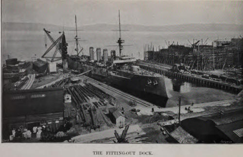
The ships launched are completed in the fitting-out dock, constructed
about two years ago, and illustrated on Plate XLIV. The engraving shows
H.M.S. Argyll under the big jib-crane. This dock has a length of 560 ft.
and a width of 172 ft., and opens directly into the channel of the Clyde.
The depth of water is never less than 28 ft., so that warships are afloat
at all states of the tide. A prominent feature in the view is the crane,
which was supplied by Messrs. George Russell and Co., Limited, of
Motherwell, and lifts 120 tons at a radius of 70 ft. It is carried on
concrete foundations and piers, which rise 20 ft. above the level of the
quay. In addition to the pier for carrying the mast of the crane, there
are similar supports for each of the back legs through which the crane is
anchored.
One advantage of the derrick type is that the crane may be placed close to
the edge of the quay; in this case the centre is only 7 ft. from the front
of the wharf, so that the full load of 120 tons can be dealt with at an
effective outreach of 63 ft. from the quay. The maximum radius of the
heavy purchase with a load of over 60 tons is 90 ft., and of the light
purchase gear, with a load of 10 tons, 98 ft. The minimum radius of the
crane is 25 ft. There are four sets of gear: for lifting heavy loads, for
raising light weights, for derricking the jib, and for slewing; a separate
controller of the enclosed tramway type is provided for each. The main
hoisting and derricking motors are of 50 horse-power, and the others of 35
horse-power. The speed of hoisting 120 tons is 5 ft. per minute, while a
10-ton load is raised at the rate of 40 ft. per minute. Automatic brakes
are fitted for the slewing motion, and powerful hand-brakes for the
hoisting and derricking gears. All motions are controlled by one man in
the steelhouse fixed to the mast of the crane 56 ft. above the quay level.
There is on the opposite wharf of the dock a 20-ton travelling electric
crane, and throughout the Works there are many portable and hydraulic
cranes, in addition to the hydraulic and other cranes commanding the
machine tools.
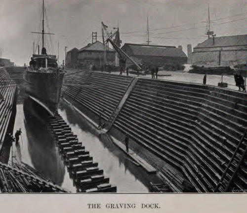
Reference may here be made to the Company's graving dock, illustrated on
Plate XLV., adjoining page 101. The length is 360 ft., and it is largely
used for docking ships for repair, as well as for cleaning ships
preparatory to trial. Our view shows a torpedo-boat destroyer in the dock.
The pumps for the emptying of the dock are electrically driven.
We may return now to our narrative of the construction of a ship, and deal
with the supplementary departments, including those of joiners, smiths,
plumbers, sheet-iron, and other workers.
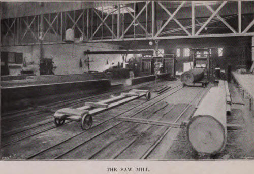
Wood-work forms a large and important item in most of Scotts' ships, as
many of them are for passenger service. We illustrate on Plate XLVI. one
of the saw-mills. It is self-contained, having its own power plant,
including a compound engine, having cylinders 151 in. and 274 in. in
diameter by 44-in, stroke. There are four vertical saw frames, the largest
having a 36-in, frame, six rollers, and two bogies to take in the heaviest
logs. In addition, there are circular saws, ranging up to 6 ft. in
diameter, a swing cross-cut saw, special planing, moulding, and turning
machines to do heavy work, and saw-sharpeners, grind-stones, punching
machines and anvils to carry out all repairs and fettling of the blades,
etc. There are also large steam- heated drying stoves, and a timber-drying
yard of about three acres in extent. The overhead travelling cranes range
up to 5 tons capacity, and the rails on which they run are extended on
columns across the yard. The saw-mill is the largest and best-equipped in
the district, and does the sawing and planing of timber for three of the
largest shipbuilding yards, as well as the general work for two other
firms.
The joiners' and cabinet-makers' shop, as we have already indicated,
occupies two floors of a building 240 ft. long and 52 ft. wide; while the
fourth floor is utilised for the French polishing work, as well as for
storing the completed wood-work until the vessel is ready to receive it.
Provision is also made in the same building for the model-making
department, in which replicas of nearly all ships are produced, and, being
works of art, because of their completeness, accuracy, and beauty, have
earned high awards at many Exhibitions.
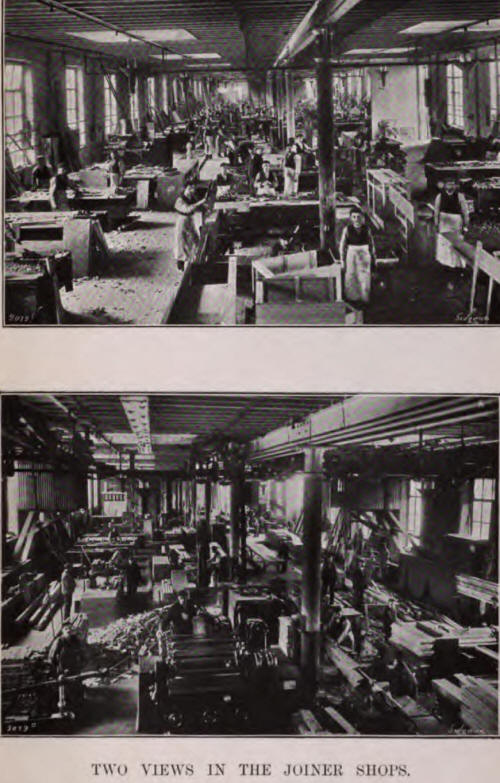
In the joiners' shops, illustrated by two engravings on Plate XLVII.,
adjoining this page, there is a complete equipment of wood-working
machines for sawing, turning, planing, moulding, sand-papering, mortising,
boring, tenoning, dovetailing, dowelling and joining. These are
electrically driven, and are grouped at three places in the length of the
shop on each floor, with benches around them, so that the joiners do not
require to carry their jobs any distance in order to have them machined.
There is also in use in connection with the department a portable electric
circular saw, which is specially useful for carpenters and joiners, etc.,
on board the ship in the dock. An electric deck- planer, of the lawnmower
form, has proved serviceable in reducing enormously the most laborious
task experienced by carpenters and joiners.
There are two large smithies convenient to the shipbuilding berths, and in
both cases the finishing department adjoins. In one case there are
fifty-four fires and eight hammers; in the other, forty fires, with five
hammers, ranging up to 15 cwt. The fires are operated by mechanical
blowers, and the smoke and waste gases are carried off by overhead
ventilating pipes. Extensive work is carried out by the smiths.
Die-stamping is largely adopted in connection with the making of
eye-plates, cleats, stanchions, clips, etc. In each finishing shop there
are band saws, radial and other drills, screwing machines, and
grindstones. Smiths' stores are arranged above the finishing shops.
The plumbers' shop is fitted with a special machine for bending pipes when
cold, as well as screwing and tapping machines, drills, saws, grinders,
and fires.
The sheet-iron department is equally well equipped, having straightening
rolls, shearing, punching, chipping, drilling, and other tools, with
various hammers; and here work is done in connection with ventilating and
other light ironwork.
In view of the warship contracts undertaken, the mechanics' shop, for work
peculiar to the ship as distinct from the propeller machinery, etc., is
extensive. The four lathes here range up to 27 ft. in length over all,
with a 14-in. headstock and a 22-ft. bed. There is useful shaping machine,
a fair-sized planer, and several drills, all adequate for the work
required, which is remarkable more, perhaps, for its great variety than
for size.
All the machinery in the yard, and in several departments in the engine
and boiler works, is run from one central station, of which two views are
given on Plate XLVIII., opposite. The electric generators occupy one side
of the power station, and the air compressors and hydraulic pumps the
other. Steam at 200 lb. pressure is supplied by one marine cylindrical,
and four Babcock and Wilcox water-tube, boilers, with superheater, coal
conveyors, and mechanical stokers.
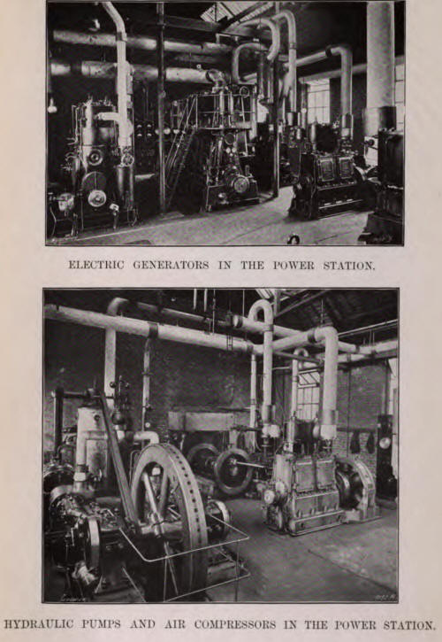
There are three electric generating sets, with a total capacity of 1200
kilowatts, the voltage being 240. They are illustrated on Plate XLVIII.,
facing this page. The engines are of the high-speed, enclosed, forced
lubrication, condensing type. The current is distributed from a
switchboard in the power station by overhead mains, with three-way
distributing panels in the various departments. The motors, of which there
are about 130 in the shipbuilding department alone, are of the two- and
four-pole type, partly or entirely enclosed, and mostly of 10 to 20
electric horsepower. Are lamps are used for lighting, but the shops and
offices are also illumined by 16 and 32 candle-power incandescent lamps.
Plugs are arranged at various points throughout the yard for portable
lights, and for connecting mains for lighting the various ships while
being completed in the docks.
Hydraulic power at 800 lb. pressure is generated by two high-pressure
pumps, with steam cylinders 15 in. in diameter, and rams 4 in. in
diameter. There are separate accumulators for each. The pressure pipes are
led underground throughout the Works to the various hydraulic tools
already referred to.
There are two air compressors for supplying power for the pneumatic tools.
The combined capacity is 1800 cubic feet of free air per minute. Each has
two steam cylinders 6 in. in diameter, working respectively high- and
low-pressure air cylinders 15 1/4 in. and 21 1/4 in. in diameter, the
stroke being 18 in. The hydraulic pumps and the air compressors are
illustrated on Plate XLVIII., facing page 104.
As we have already stated, part of the power generated in this station is
utilised at the engine works, to which we may now turn our attention.
|

